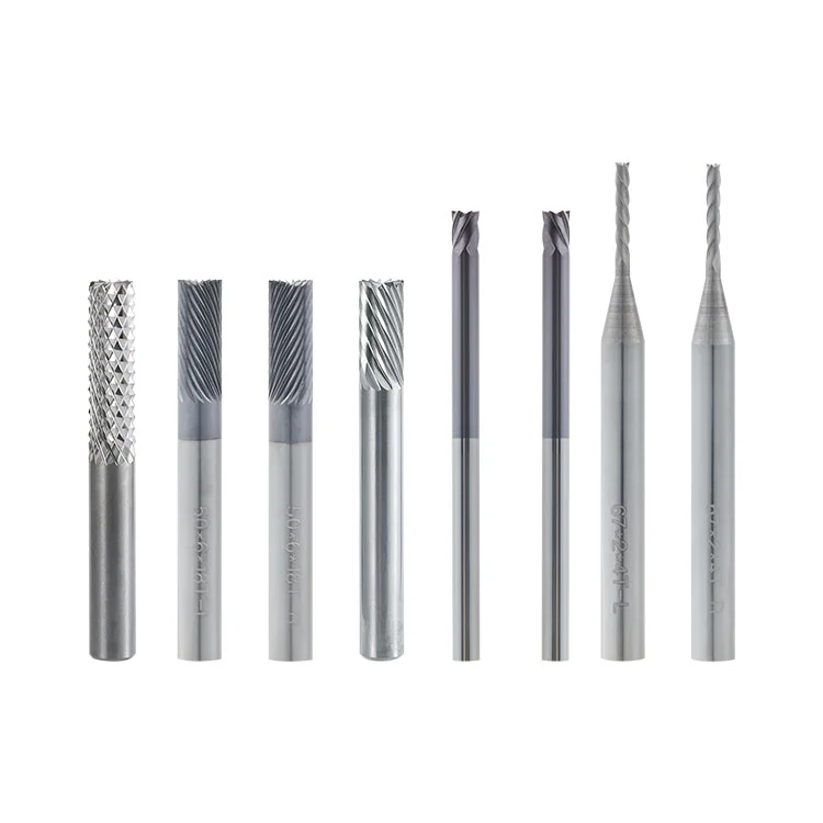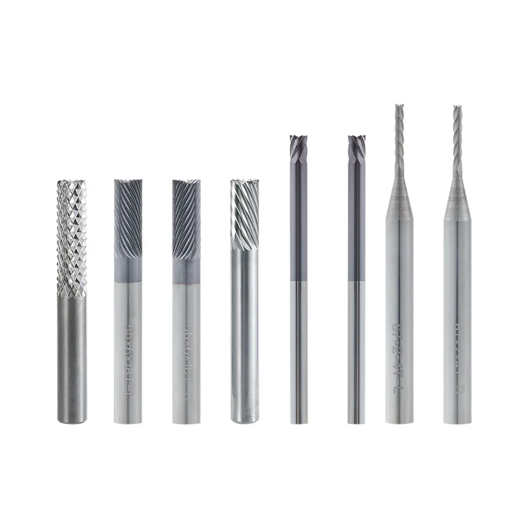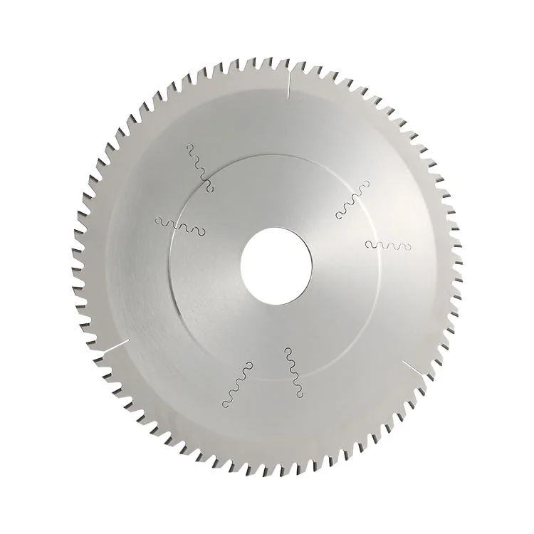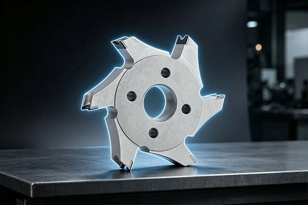

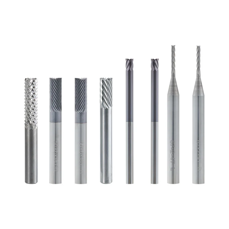
Dongguan Weicheng Electronic Co., Ltd. develops PCB cutting tools for industrial board processing, including the Carbide PCB Edge Beveling Cutter, a solid cemented carbide tool designed for gold finger beveling and chamfering. With a straight shank structure and a passivated, mirror-polished cutting edge, this cutter helps produce smooth inclined surfaces while reducing the risk of scratching or peeling the gold-plated layer during PCB connector preparation.
1. Why Gold Finger Beveling Matters
2. How the Beveling Process Works
3. Benefits of Carbide Construction
4. Passivation and Mirror Polishing
5. Choosing the Right Cutter Size
Gold fingers are conductive contact areas located along the edge of a printed circuit board. They are commonly used to connect a PCB with a compatible slot or connector. Before insertion, the ends of the gold fingers may require beveling to create an inclined guiding surface.
A properly processed bevel helps guide the board into the connector and supports smooth insertion and removal. The condition of the gold-plated surface is particularly important because scratches, peeling or uneven edges can affect the contact area and the finished board's appearance.
In automated PCB production, a dedicated beveling cutter is used to machine the board edge. Its cutting-edge condition, dimensional accuracy and compatibility with the machine all influence the consistency of the finished bevel.
The carbide cutter is clamped onto the spindle of an automatic PCB beveling machine. During operation, the tool rotates at high speed while the PCB is conveyed through the machine at a controlled feed speed.
The end of the gold finger contacts the rotating cutting edge, which mills the board edge to form an inclined guiding surface. The process is designed for continuous machining and can produce a consistent bevel when the machine setup and feeding conditions are properly controlled.
One important point is that the cutter itself does not determine the bevel angle. The bevel angle is preset and adjusted by the beveling machine. The cutter is a straight-shank tool, and the machine configuration determines the required processing angle.
The cutter is manufactured from ultra-fine-grain cemented carbide, also commonly referred to as tungsten steel. This material offers high hardness and wear resistance, making it suitable for repeated cutting operations in PCB manufacturing.
Its solid carbide construction supports the cutting performance required for continuous gold finger chamfering. Tool selection should nevertheless consider the board material, machine spindle, cutting parameters and production volume.
For boards with high glass fiber content or high inorganic filler content, tool wear may increase. These materials should be evaluated through sample processing to confirm cutting quality and tool compatibility before mass production.
The condition of the cutting edge is especially important when machining gold-plated PCB edges. An untreated sharp edge or a damaged cutting edge may create scratches, friction or localized stress during the beveling process.
Passivation and mirror polishing help remove sharp points along the cutting edge and produce a smoother contact surface. This can reduce friction against the gold-plated layer and lower the risk of gold peeling during machining.
However, the cutter is only one factor affecting the final result. Gold layer adhesion, board condition, spindle runout, dust removal and feeding speed also need to be considered. First-article inspection is recommended before continuous production.
Choosing a cutter based only on its diameter can lead to installation or processing problems. The tool must match the spindle, collet and available installation space of the beveling machine.
The product specification range includes different combinations of cutter diameter, tooth quantity, shank diameter and length. Listed cutter diameters include 1.5 mm, 2 mm, 3 mm, 3.175 mm, 4 mm, 6 mm and 6.35 mm. Shank diameters include 3.175 mm, 6 mm and 6.35 mm, depending on the model.
Before ordering, confirm the following information:
● Cutter diameter: Check the required diameter against the machine's installation space and processing configuration.
● Shank diameter: Match the shank to the spindle and collet to ensure secure clamping.
● Tool length: Confirm the cutting length and total length required for the machine setup.
● Number of teeth: Select the corresponding model according to the required machining conditions and equipment compatibility.
● Board material: Provide the PCB type and relevant material characteristics for tool evaluation.
Providing a machine model, existing cutter sample or technical drawing can help verify the required dimensions before production.
Gold finger scratches, coating peeling and uneven bevel surfaces can result from several different causes. Replacing the cutter without checking the machine and board condition may not resolve the underlying issue.
Possible causes include a chipped cutting edge, insufficient passivation, excessive tool runout, poor dust collection, excessive feeding speed or weak adhesion of the gold-plated layer. Inspect the cutter and PCB surface during first-article testing.
Surface ripples and visible tool marks may be associated with spindle or collet wear, insufficient tool rigidity, unstable board conveying or an unsuitable relationship between spindle speed and feed speed.
Uneven bevel angles may result from incorrect machine angle settings, board positioning deviations, unstable conveying or abnormal spindle runout. The bevel angle should be checked and adjusted through the machine rather than by assuming the cutter has a fixed forming angle.
High glass fiber content, poor dust extraction, excessive cutting temperature and unsuitable processing parameters can accelerate tool wear. Regular inspection helps identify changes in cutting-edge condition before they affect production quality.
Correct installation and routine maintenance help preserve tool condition and support stable processing. Before operation, inspect the cutter under suitable magnification for cracks, chips or edge damage. The shank and collet should be clean, and tool runout should be checked before machining.
During production, keep the dust collection system operating to remove glass fiber and other cutting debris. Avoid sudden changes in board feeding speed, which can introduce impact loads and increase the risk of cutting-edge damage.
After processing, remove dust with a soft brush and store the cutter in a dry place. Avoid contact between the cutting edge and hard objects. When the edge becomes dull, professional regrinding may restore its cutting capability. Runout should be checked again after grinding before the tool is reinstalled.
Trial cutting and first-article inspection should be carried out after installation or tool replacement. Check the bevel angle, surface finish and gold-plated layer condition before proceeding with continuous production.
A: It is used on PCB beveling machines to chamfer the ends of gold-plated gold fingers. The process creates an inclined guiding surface to support PCB insertion into connectors.
A: No. The cutter has a straight-shank structure without a fixed forming angle. The bevel angle is set and adjusted by the PCB beveling machine.
A: Passivation and mirror polishing help remove sharp points and create a smoother cutting edge. This helps reduce friction, scratching and the risk of peeling on the gold-plated surface.
A: Thin FPC boards can be evaluated for chamfering. The board feeding speed should be reduced to limit cutting impact, and sample testing is recommended before production. FPC boards with thick reinforcement plates also require prior evaluation.
A: Possible causes include a chipped or insufficiently polished cutting edge, excessive tool runout, dust trapped between the tool and board, high feeding speed or poor adhesion of the gold-plated layer. These factors should be checked individually.
A: Check the spindle and collet specifications, installation space, required tool length and machine configuration. The cutter dimensions should be confirmed against the equipment drawing or an existing tool sample.
A: Yes. Professional regrinding can restore a dull cutting edge when the tool condition allows it. After grinding, inspect the cutting edge and recheck tool runout before reinstalling it.
A: Carry out first-article testing to confirm the bevel angle, surface finish and gold-plated layer condition. Also check cutter installation, spindle runout, collet cleanliness, board positioning and dust collection.
Consistent PCB gold finger beveling requires the right combination of carbide tool construction, cutting-edge preparation, machine compatibility and process control. Evaluating these factors before production helps manufacturers maintain stable bevel quality and reduce avoidable surface defects.
Looking for a carbide cutter for PCB gold finger beveling?
Send your machine specifications, cutter drawing or sample requirements to our team.
Send an Inquiry