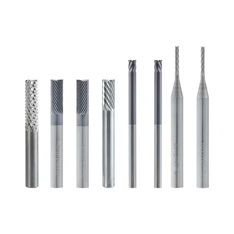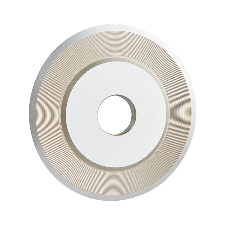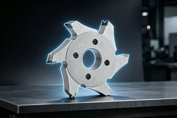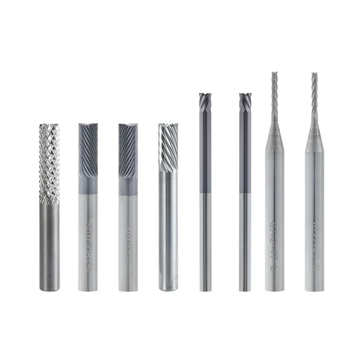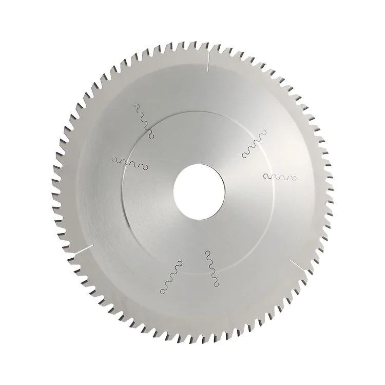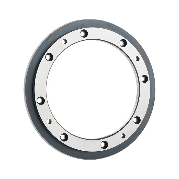

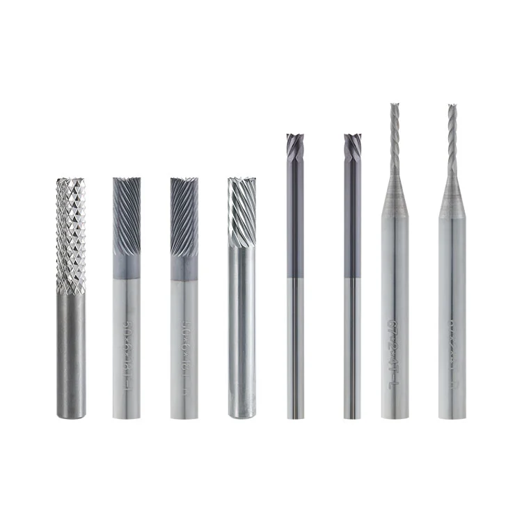
As a Professional Supplier, Winway provides the Carbide PCB Edge Beveling Cutter, a solid cemented carbide tool designed for automatic PCB beveling machines. It is used for beveling and chamfering the ends of PCB gold-plated gold fingers. Featuring a straight shank structure, the cutting edge undergoes passivation and mirror polishing to produce smooth inclined surfaces. This helps reduce scratches and peeling of the gold-plated layer while meeting connector insertion and extraction requirements. The cutter is suitable for continuous mass production of PCB gold finger chamfering.
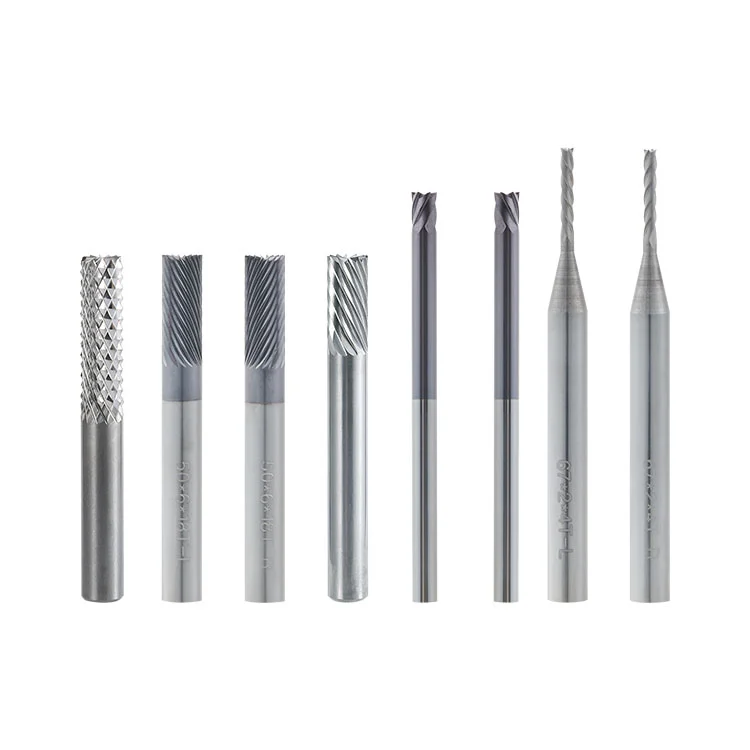
The Carbide PCB Edge Beveling Cutter is a special cutting tool for PCB beveling machines. It is integrally manufactured from ultra-fine-grain cemented carbide (tungsten steel) and features a straight shank for spindle mounting. During operation, the outer circular cutting edge rotates at high speed while the PCB board passes through the machine at a constant speed. The tool machines the guiding inclined surface at the end of the gold-plated gold finger for subsequent connector insertion.
The cutter is clamped onto the spindle of the beveling machine and rotates at high speed. The PCB board is fed at a constant speed by the crawler conveying mechanism, allowing the end of the gold finger to continuously contact the rotating cutting edge. The bevel angle is preset and adjusted by the machine equipment rather than formed by the cutter itself.
The cutting edge mills the board edge to create a uniform inclined surface in one pass. Passivation and polishing weaken sharp points along the edge, helping reduce tearing and friction against the gold-plated layer during cutting and lowering the risk of gold peeling.
● Solid carbide construction: Integrally made of ultra-fine-grain cemented carbide for high hardness and wear resistance.
● Passivated cutting edge: The cutting edge is passivated and polished to eliminate sharp points and reduce scratching of the gold-plated surface.
● Straight shank design: Supports spindle clamping on compatible automatic PCB beveling machines.
● Stable cutting: Continuous cutting with assembly-line board feeding helps produce consistent inclined surfaces.
● Reduced coating damage: The polished cutting edge helps reduce friction-related gold peeling and scratching during gold finger chamfering.
The following specifications cover different cutter diameters, tooth quantities, shank diameters and lengths. Select the Carbide PCB Edge Beveling Cutter according to the spindle and tool holder requirements of the beveling machine.
| Ordinal | Diameter (D) | Number of Teeth (P) | Shank Diameter (d) | Length (L1) | Total Length (L) |
| 01 | 2 | 4 | 6 | 15 | 50/67 |
| 02 | 3 | 6 | 6 | 15 | 50/67 |
| 03 | 4 | 8 | 6 | 15 | 50/67 |
| 04 | 6 | 12 | 6 | 17 | 50/67 |
| 05 | 6.35 | 18 | 6.35 | 18 | 50/67 |
| 06 | 3.175 | 6 | 3.175 | 4.5 | 50 |
| 07 | 2 | 4 | 3.175 | 14 | 54 |
| 08 | 3.175 | 10 | 3.175 | 12 | 54 |
| 09 | 2 | 4 | 3.175 | 14 | 67 |
| 10 | 3.175 | 6 | 3.175 | 16 | 67 |
| 11 | 1.5 | 4 | 6 | 14 | 50 |
| 12 | 2 | 4 | 6 | 14 | 50 |
| 13 | 6 | 18 | 6 | 16 | 50 |
| 14 | 2 | 4 | 6 | 14 | 67 |
| 15 | 3 | 6 | 6 | 14 | 67 |
| 16 | 4 | 8 | 6 | 14 | 67 |
| 17 | 6 | 18 | 6 | 16 | 67 |
| 18 | 6 | 12 | 6 | 30 | 80 |
| 19 | 6.35 | 12 | 6.35 | 25 | 50 |
● FR-4 rigid boards: Bevel chamfering of gold-plated gold fingers in PCB assembly-line production.
● Memory sticks: Gold finger inclined surface forming to support connector insertion.
● Communication boards: Gold finger chamfering for communication circuit boards.
● Industrial control boards: Inclined surface processing for industrial control PCB connectors.
● Test boards: Gold finger bevel processing for PCB test boards.
● Continuous production: Mass gold finger bevel processing using automatic PCB beveling machines.
Thin FPC boards can also be evaluated for chamfering. Board feeding speed should be reduced, and sample testing should be conducted in advance.
● High-filler special boards: Boards with high glass fiber content or high inorganic filling may accelerate tool wear and increase the risk of gold peeling or edge chipping.
● Protruding copper: Workpieces with copper nodules or residual copper protrusions along the board edge may collide with the cutting edge during feeding.
● Metal plates: Not suitable for large-area cutting of aluminum substrates or other metal plates.
● Poor dust control: Production lines without effective dust collection may accumulate glass fiber dust and increase cutting friction.
● Excessive cutting load: Board feeding speed and cutting pressure exceeding the tool's rated working conditions should be avoided.
● Poor coating adhesion: PCB boards with weak gold-plated layer adhesion may develop peeling defects regardless of cutter condition.
Misunderstanding: The tool angle directly determines the bevel angle.
Correction: The Carbide PCB Edge Beveling Cutter has a straight shank structure and does not have a fixed forming angle. The bevel angle is adjusted by the beveling machine equipment, not by the cutter itself.
Misunderstanding: Ordinary PCB shank milling cutters can directly replace special gold finger bevel cutters.
Correction: Ordinary milling cutters may have sharp, untreated cutting edges. Without appropriate passivation and polishing, they can scratch the gold-plated layer and increase the risk of gold peeling.
Misunderstanding: A longer cutting edge always improves machining performance.
Correction: An excessively long cutting edge can reduce tool rigidity, cause cutting vibration and leave tool marks or scratches on the gold finger coating.
Misunderstanding: A larger cutter diameter always increases processing efficiency.
Correction: The diameter must match the spindle installation space and machine configuration. Large-diameter tools should not be selected without checking compatibility.
1. First-article inspection: Conduct trial cutting before mass production to confirm the bevel angle and gold finger coating condition.
2. Runout control: Do not use cutters with excessive radial runout, which may cause surface ripples and gold finger scratches.
3. Clean installation: Do not install the cutter when the shank or collet is contaminated with oil or dust, or shows signs of wear.
4. Tool condition: Cutters with chipped edges, notches or cracks must not be used.
5. Stable feeding: Avoid sudden changes in board feeding speed, as impact loads may cause cutting edge chipping.
6. Safe shutdown: Do not forcibly drag the board to stop the machine during processing, as this may cause horizontal scratches on the gold-plated surface.
Possible causes: Chipped cutting edge, insufficient passivation or polishing, excessive tool runout, poor dust collection, glass fiber dust trapped between the cutting edge and board surface, excessive board feeding speed, or insufficient adhesion of the PCB gold-plated layer.
Possible causes: Spindle or collet wear, insufficient tool rigidity, mismatch between board feeding speed and spindle speed, or unstable board conveying and positioning.
Possible causes: Incorrect bevel angle settings on the machine, board conveying or positioning offset, tool wear, or abnormal spindle runout.
Possible causes: High glass fiber content in the board, poor dust collection, excessive cutting temperature, or unsuitable cutting parameters.
Possible causes: Copper nodules or foreign objects on the board striking the tool, or excessive feeding impact.
1. Before installation: Check the cutting edge for chipping and cracks under a microscope. Clean the tool shank and collet, and measure tool runout.
2. During processing: Keep the dust collection system running to remove cutting dust and reduce cutting edge wear.
3. After processing: Clean dust from the tool with a soft brush. Avoid touching the cutting edge with hard objects and store the cutter in a dry environment.
4. After dulling: Send the cutter for professional grinding. Recheck runout after grinding before reinstalling it. Grinding repairs the cutting edge only and does not create a forming angle.
5. Storage: Store cutters separately and protect their cutting edges to prevent collision damage.
A1: Thin FPC gold fingers can be processed. Reduce the board feeding speed to limit cutting impact. FPC boards with thick reinforcement plates should undergo sample evaluation in advance.
A2: Not necessarily. Gold peeling can be affected by cutting edge condition, cutting parameters, dust friction, PCB gold plating processes and coating adhesion. Check these factors individually during first-article inspection.
A3: No. The Carbide PCB Edge Beveling Cutter is a straight-shank tool for beveling machines. The bevel angle is adjusted by the machine equipment, allowing the same compatible cutter to process different angles.
A4: Yes. Cemented carbide supports professional regrinding. Grinding repairs the cutting edge, and the cutter does not require a forming angle to be machined.
Address
Building 17, Yonglida Tiansheng Industrial Park, No. 50 Gangkou Avenue, Wanjiang District, Dongguan City, Guangdong Province, China
Tel