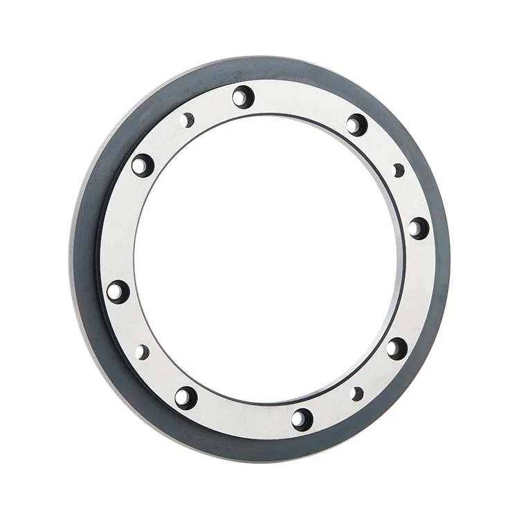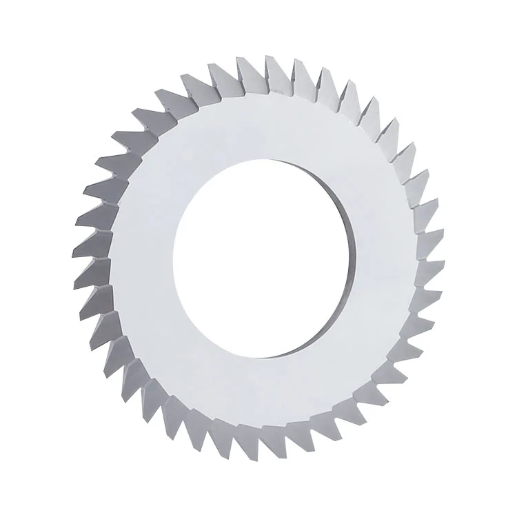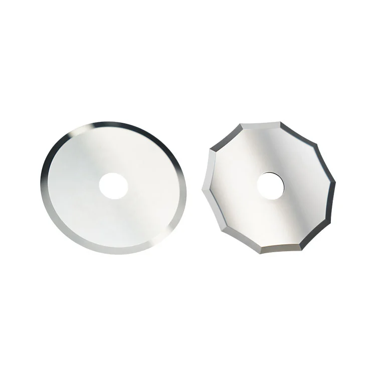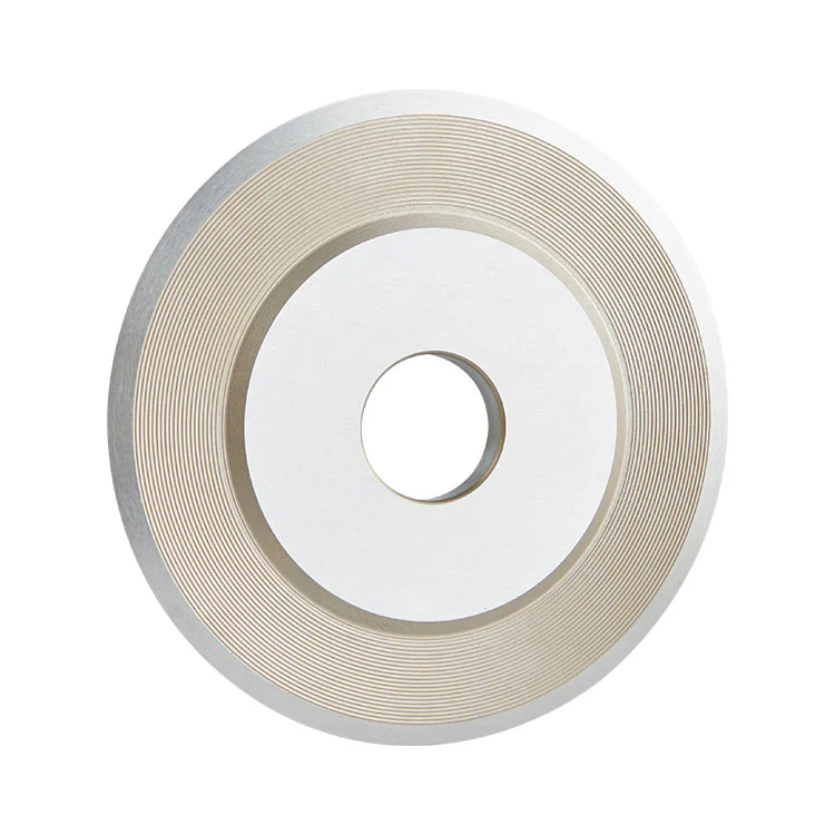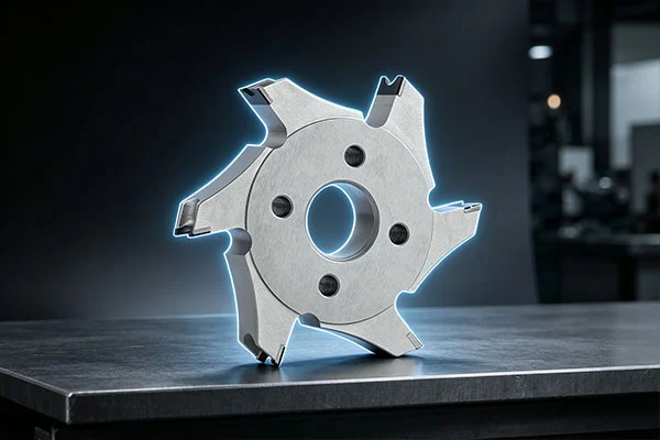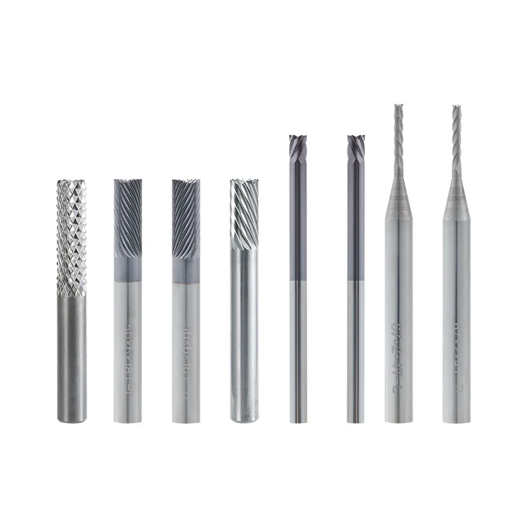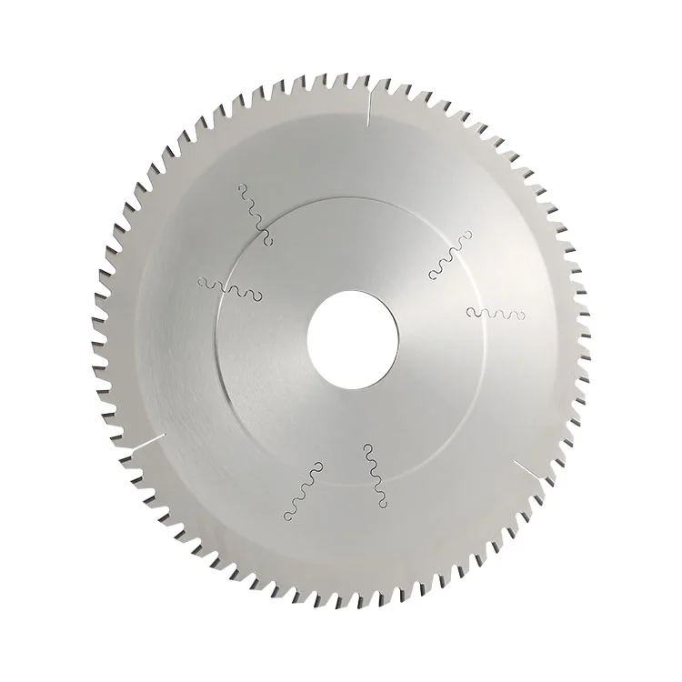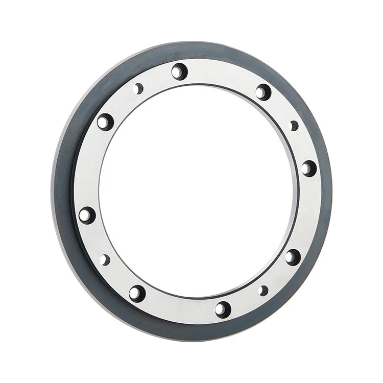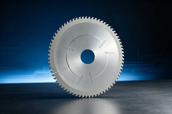
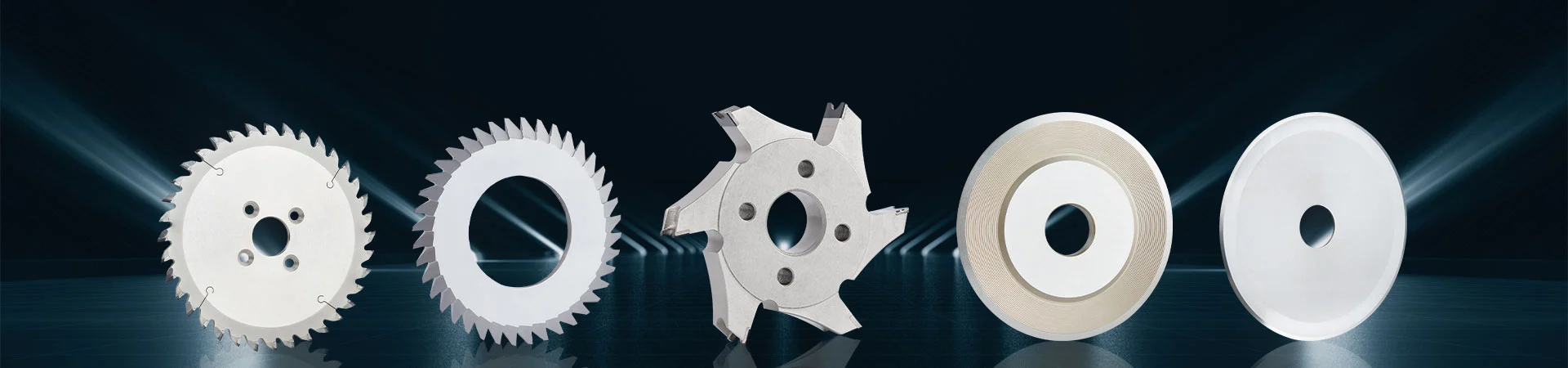
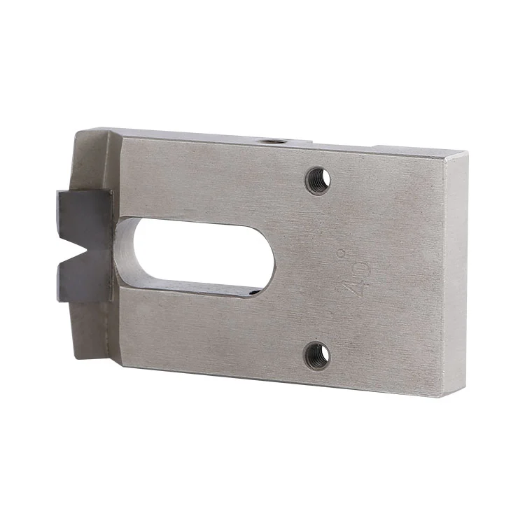
As a China Manufacturer, Winway offers the Carbide PCB Pneumatic Bevel Cutter, a special blade matched with pneumatic beveling machines. It adopts a combined structure of a blade substrate welded with a hard alloy tungsten steel cutting edge. Driven by the pneumatic feed of the equipment, it is mainly used for PCB gold finger bevel processing. The cutting edge features high hardness and long wear resistance, delivering a uniform bevel angle and smooth chamfer surface. It meets the requirements of mass chamfering production of PCB gold fingers and is compatible with various PCB pneumatic beveling equipment.
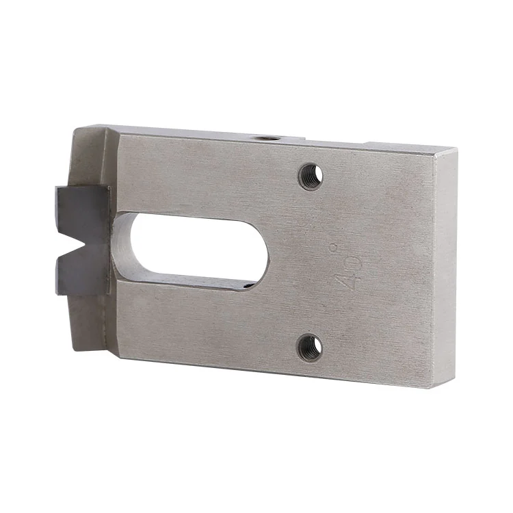
Carbide PCB Pneumatic Bevel Cutter: A sheet bevel cutting blade made by welding an ultra-fine-grain hard alloy (tungsten steel) cutting edge onto an alloy steel substrate. Matched with a pneumatic gold finger beveling machine, it completes bevel chamfering on the PCB gold finger area through pneumatic feeding.
The blade is fixed on the tool holder of the pneumatic beveling machine. The cylinder provides stable pressure to push the blade into contact with the high-speed moving PCB gold finger area at a uniform speed. The tungsten steel cutting edge cuts the gold finger edge at a preset angle, completes bevel chamfering in one pass and removes sharp edges and burrs. The pneumatic pressure can be fine-tuned to control cutting depth and avoid copper foil damage to gold fingers caused by excessive cutting.
Non-standard customization is available.
| Parameter Code | Name | Description |
| L | Total blade length | Customized according to equipment model |
| L1 | Cutting section length | Customized based on effective width of processed gold finger |
| b | Blade width | Matching the installation space of tool holder |
| a | Blade thickness | Matches mounting groove of tool holder |
Mounting hole: Strip adjusting hole, supporting fine adjustment of front and rear position.
Cutting edge: Tungsten steel welded edge, customizable bevel angle upon customer request (common 30°/45°).
● PCB gold finger chamfering: Bevel chamfering processing for PCB circuit board gold fingers (FR-4 board, BT board, high Tg board).
● Connector contact pin processing: Slope processing for connector contact pins to remove sharp edges of gold fingers and prevent scratches during plugging.
● PCB prototype processing: Gold finger chamfering process for PCB prototype boards.
● Mass production: Gold finger chamfering process for PCB mass production boards.
● Pneumatic equipment: Chamfering operation matched with all kinds of pneumatic beveling machines.
● Material limitation: Cannot process thick metal plates or solid metal parts; only for thin copper foil chamfering of PCB gold fingers.
● Processing limitation: Not for heavy stock removal rough milling; only suitable for precision micro chamfering.
● Dust conditions: Not suitable for environments with massive glass fiber dust without dust collection, which will accelerate cutting edge wear.
● Equipment conditions: Cannot be used on old equipment with unstable pneumatic pressure and violent vibration.
● Foreign objects: Forbidden to cut boards with hard impurities or foreign objects, as they can easily cause edge chipping.
Misconception: Larger angle means better performance.
Correction: The angle shall be selected according to connector specifications. An excessively large angle will easily reduce the effective copper thickness of gold fingers and affect electrical conduction.
Misconception: A thicker blade brings longer service life.
Correction: Blade thickness must match the width of the tool holder groove. Mismatched thickness causes vibration and a wavy bevel surface.
Misconception: Blades for all pneumatic beveling machines are universal.
Correction: Different brands of beveling machines differ in mounting hole, total length and cutting edge position. Blades cannot be interchanged directly; mounting dimension verification is required.
Misconception: A wider tungsten steel edge means longer service life.
Correction: An overly wide cutting edge increases cutting resistance and can easily lead to board shifting and gold finger scratching.
1. Confirm the tool holder is locked tightly and the blade is not loose before mounting. Power-on is forbidden without locking.
2. Pneumatic pressure shall not exceed the rated upper limit of the equipment. Excessive pressure may cause edge chipping and gold finger damage.
3. Stacked or overlapped board processing is forbidden. Single-board feeding only.
4. Stop using the blade and remove it for inspection if the cutting edge hits a hard object or tool collision occurs.
5. Long-time processing without a dust collection device is forbidden. Accumulated dust will scratch the cutting edge and board surface.
6. Reverse blade installation is forbidden, as it will directly scratch gold fingers.
Possible causes: Loose blade, unstable pneumatic pressure, worn tool holder or dull cutting edge.
Possible causes: Chipped cutting edge, excessive feed speed, overly high pressure or cutting edge without edge passivation.
Possible causes: Fluctuating board feeding speed, offset blade installation or unstable cylinder pressure.
Possible causes: Foreign objects inside the board, instant over-pressure, board collision or eccentric blade clamping.
● Clean glass fiber dust and copper scraps from the blade edge and tool holder after each shutdown.
● Inspect the cutting edge regularly and replace or regrind it in a timely manner if notches or wear are found.
● Store blades in a protective box. The cutting edge shall not directly contact hard objects to prevent collision damage.
● Apply a thin layer of anti-rust oil on the cutting edge for long-term storage and keep it in a dry environment.
● Clean the mounting surface of the tool holder when removing and reinstalling the blade to ensure a flat fit.
A1: Yes. The tungsten steel cutting edge can be reground to restore the bevel angle and reduce replacement costs. Regrinding is available as long as the substrate is not deformed.
A2: Yes. Common angles of 30° and 45° are available, and other special angles can be customized.
A3: First, check whether the cutting edge is chipped. Then reduce pneumatic pressure and feeding speed, and perform edge passivation treatment.
A4: Check whether the blade is installed in parallel, inspect tool holder wear and feeding guide offset, and recalibrate the blade position.
Address
Building 17, Yonglida Tiansheng Industrial Park, No. 50 Gangkou Avenue, Wanjiang District, Dongguan City, Guangdong Province, China
Tel