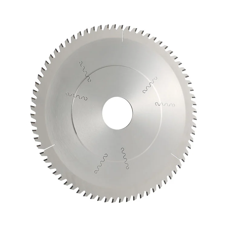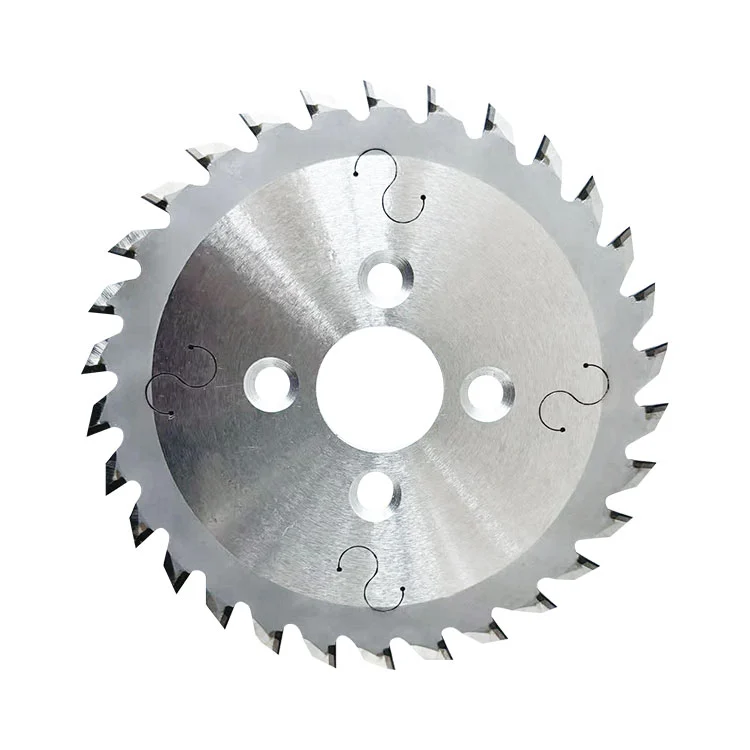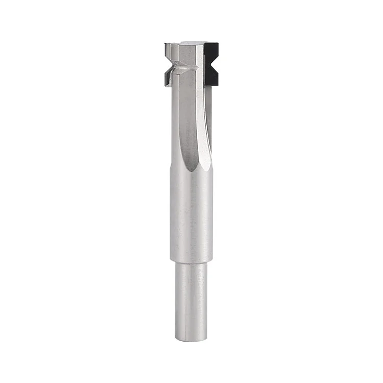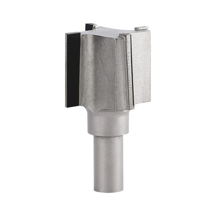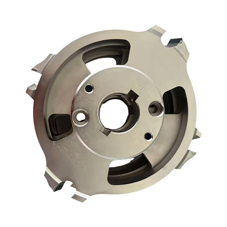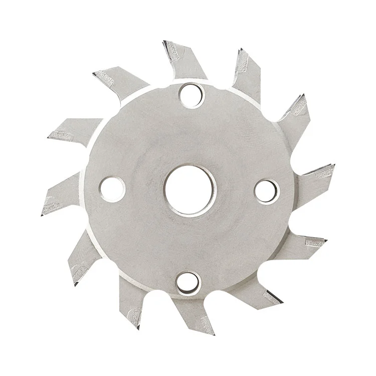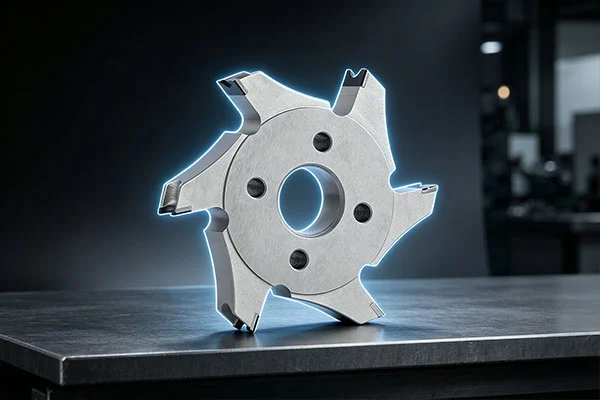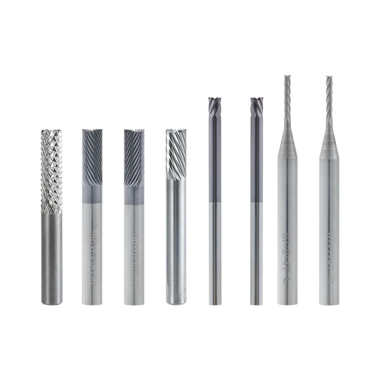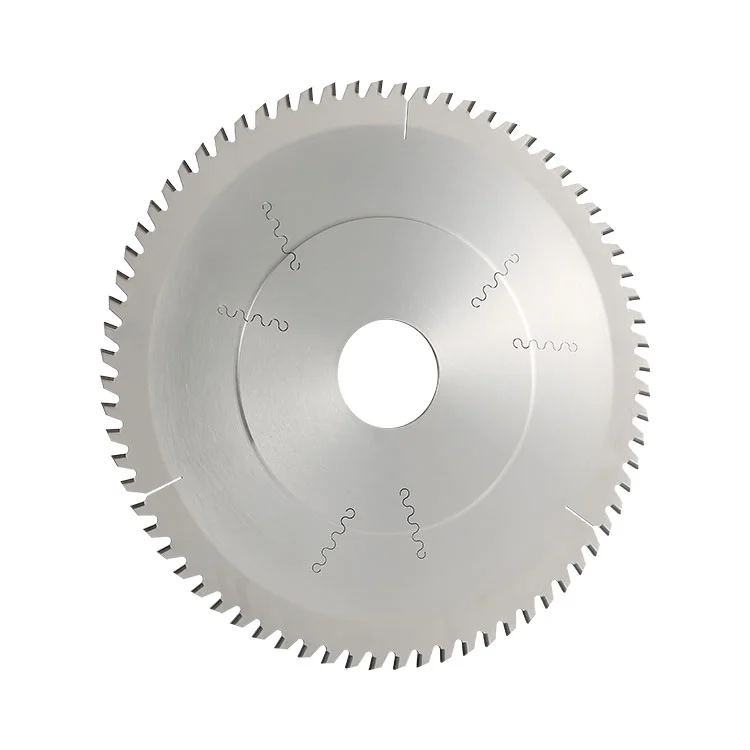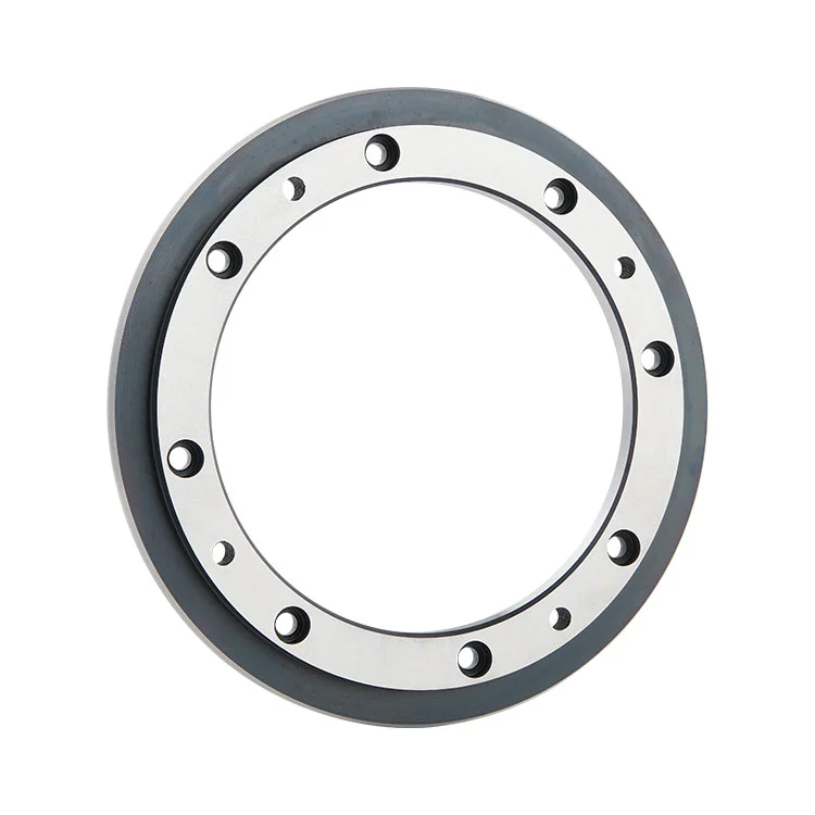

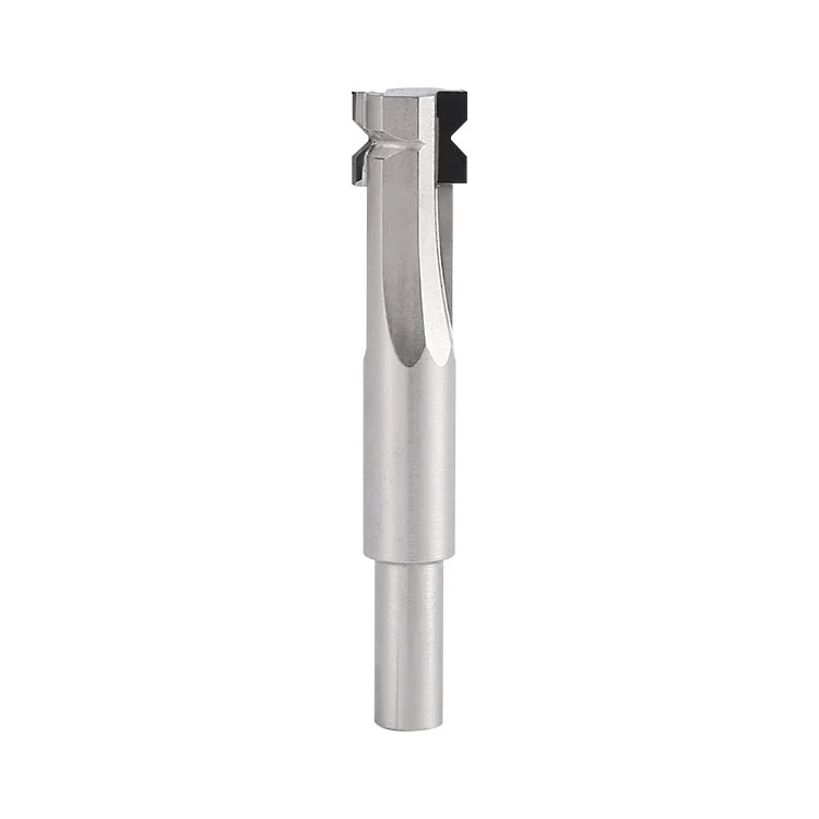
For manufacturers sourcing a PCD Shank Corner Radius Cutter for PCB production, Winway offers a solution designed for consistent edge rounding and long-term machining performance. Sharp corners left by routing, panel sizing and contour forming can scratch base materials, copper foil and dry film during subsequent processes, while also posing handling risks to operators. This cutter uses a PCD diamond tip joined to an alloy steel substrate through vacuum-controlled high-temperature welding, followed by precision grinding to produce smooth, rounded PCB edges. Its diamond cutting edge provides higher hardness, better wear resistance and lower heat generation than traditional tungsten steel alternatives. The combination of a wear-resistant tip and a rigid, tough alloy steel shank helps reduce rapid tool wear, edge chipping and frequent tool changes in mass production. Winway supports wholesale purchasing and customized orders for different PCB corner rounding requirements.
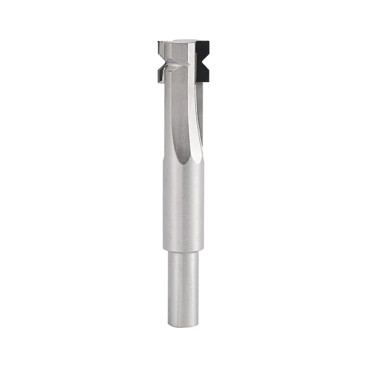
PCD Shank Corner Radius Cutter: A PCB dedicated forming tool made of heat-treated high-strength alloy steel as the shank substrate. The front tip seat is bonded with polycrystalline diamond (PCD) tip via controllable high-temperature welding and precisely ground. It is used to machine right-angle PCB edges into standard R arcs, meeting forming requirements of smooth edges without sharp corners, burrs or edge chipping.
1.Ultra-wear-resistant PCD diamond cutting edge: Diamond features extremely high hardness, great resistance to glass fiber and dust abrasion. Its service life is far longer than ordinary tungsten steel cutters, suitable for stable mass production.
2.Mirror polished cutting edge: High gloss polishing on cutter teeth reduces cutting resistance significantly, effectively preventing glass fiber pulling, board whitening, edge chipping and fuzzing.
3.Advanced welding technology: PCD tip and alloy steel substrate are integrated by welding. The heating, constant temperature and cooling curves are strictly controlled to restrain diamond graphitization and release welding thermal stress. The welding seam is full without pores or cold solder joints, featuring high bonding strength and resistance to cutting thermal shock. It is not easy to suffer desoldering or tooth loss during high-speed machining.
4.Heat-treated alloy steel shank substrate: After quenching and tempering heat treatment, it owns good rigidity, deformation resistance and fracture toughness. Light weight and excellent dynamic balance under high-speed rotation ensure uniform rounded corners and stable dimensional accuracy.
5.Standard 2-tooth cutting structure: Balanced cutting load, smooth chip removal and low vibration to form smooth and uniform rounded arcs.
6.Full coverage of multiple R-specifications: Supports mainstream PCB R corner specifications R0.2/R0.3/R0.5, matching various finished board appearance standards.
| Item | Parameter Specification |
| Product Name | PCD Shank Corner Radius Cutter |
| Cutting Diameter | 9.5mm |
| Overall Length | 55mm |
| Shank Diameter | 6mm |
| Teeth Number | 2 Teeth |
| Optional Radius | R0.2 / R0.3 / R0.5mm |
| Cutting Edge Material | PCD Polycrystalline Diamond |
| Shank Substrate Material | Heat-treated High-strength Alloy Steel |
| Machining Requirement | Selected Radius | Applicable Scenario | Process Suggestion |
| Fine small boards, high appearance requirement | R0.2 | Precision thin boards, fine circuit boards | Reduce feed rate, stable low-speed cutting |
| General standard corner rounding process | R0.3 | Most mass-produced PCB boards | Standard universal option with highest yield |
| Thick boards, large arc appearance requirement | R0.5 | Thick boards, large chamfer finished boards | Two-pass cutting to avoid edge chipping |
Clamping Requirement: Use high-precision ER collet. Clean the shank to remove dust and oil. Tool runout shall be controlled within 0.003mm to prevent vibration and edge chipping. Do not apply excessive clamping force on alloy steel shank to avoid shank deformation.
Tool Setting Requirement: Set cutting depth precisely. Over-depth cutting and excessive single-pass cutting are forbidden to prevent overload wear on tool tip.
Board Fixing: Boards must be tightly pressed and flat without warpage or looseness. Vibration is the primary cause of corner chipping and uneven corner radius.
Cutting Recommendation: For high glass fiber boards and thick boards, adopt multiple shallow cuts instead of full depth single-pass cutting.
| Abnormal Phenomenon | Root Cause | Solution |
| Board edge chipping, glass fiber cracking | Excessive feed rate, low spindle speed, board vibration, slight cutting edge damage | Reduce feed rate, increase spindle speed, re-clamp board, replace tool |
| Uneven corner radius | Large spindle runout, loose collet, warped board | Replace collet, calibrate spindle, flatten board |
| Rapid tip wear and flattening | High filled board, overloaded parameters, insufficient cooling | Optimize parameters, strengthen air cooling, adopt multi-pass cutting |
| Fuzzing and pulling marks on board edge | Blunt cutting edge, climb milling, accumulated dust | Replace tool, switch to down milling, clean dust |
| Tip peeling or tooth loss | Overheat, overload cutting, weld failure under high temperature | Reduce cutting depth, enhance cooling, adjust parameters |
| Shank deformation | Excessive clamping force, long-time high-speed overload | Reduce collet locking force, verify spindle parameters |
1.Cleaning: Clean cutting edge dust with soft brush after each shutdown. Do not touch diamond edge with hard objects.
2.Storage: Store each tool separately in tool box to avoid collision. PCD cutting edge will be scrapped once knocked. Keep alloy steel shank from rusting.
3.Inspection: Inspect cutting edge under microscope before mass production. Do not use if there are notches or chipped teeth.
4.Material Restrictions: Do not cut metal, foreign matters or impurity boards to avoid impact damage on tool tip.
5.Long-term Storage: Wipe and apply anti-rust oil for long-term storage, keep in dry environment to prevent alloy steel shank rust.
A1: The diamond cutting edge is ultra-sharp with mirror polishing. It performs shear cutting without pulling glass fiber, so it is better than tungsten steel cutters to prevent edge chipping, whitening and fuzzing.
A2: High glass fiber and high filler boards are highly abrasive. Fast feed rate, deep cutting depth and insufficient cooling will cause continuous high-temperature friction on the tip and lead to rapid wear. This is caused by mismatched parameters and board material instead of tool quality defect.
A3: Yes. PCD tools can be sent back for precision regrinding and polishing to restore cutting performance for multiple reuses with good cost performance. The remaining PCD tip margin will be evaluated during regrinding, and alloy steel substrate can be reused.
A4: No. Radius determines the arc forming dimension. Select the correct R value strictly according to drawing requirements.
A5: Alloy steel shank is lighter, delivers better dynamic balance at high speed and less resonance. It has superior toughness and impact resistance to avoid breakage with better cost. Please control collet locking force to prevent shank damage.
A6: Our controllable high-temperature welding adopts step heating and cooling process with tightly locked temperature window. It ensures welding strength while preventing diamond graphitization and protecting original wear resistance of cutting edge.
Address
Building 17, Yonglida Tiansheng Industrial Park, No. 50 Gangkou Avenue, Wanjiang District, Dongguan City, Guangdong Province, China
Tel