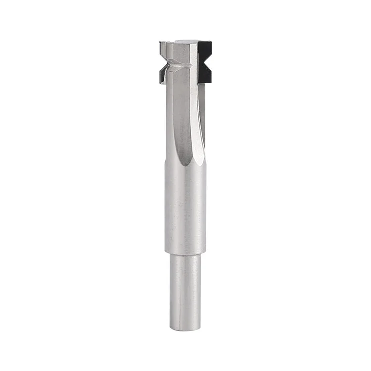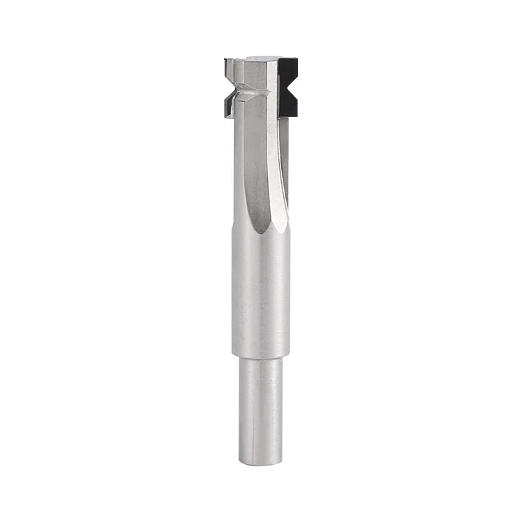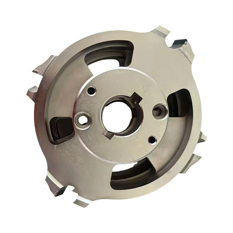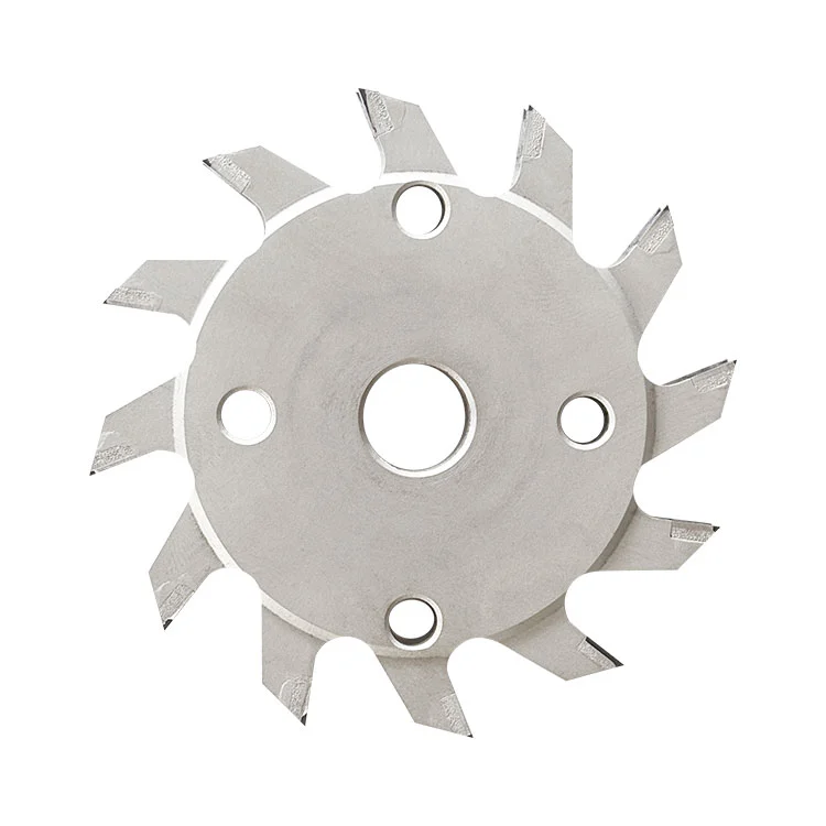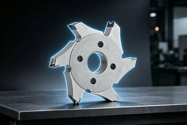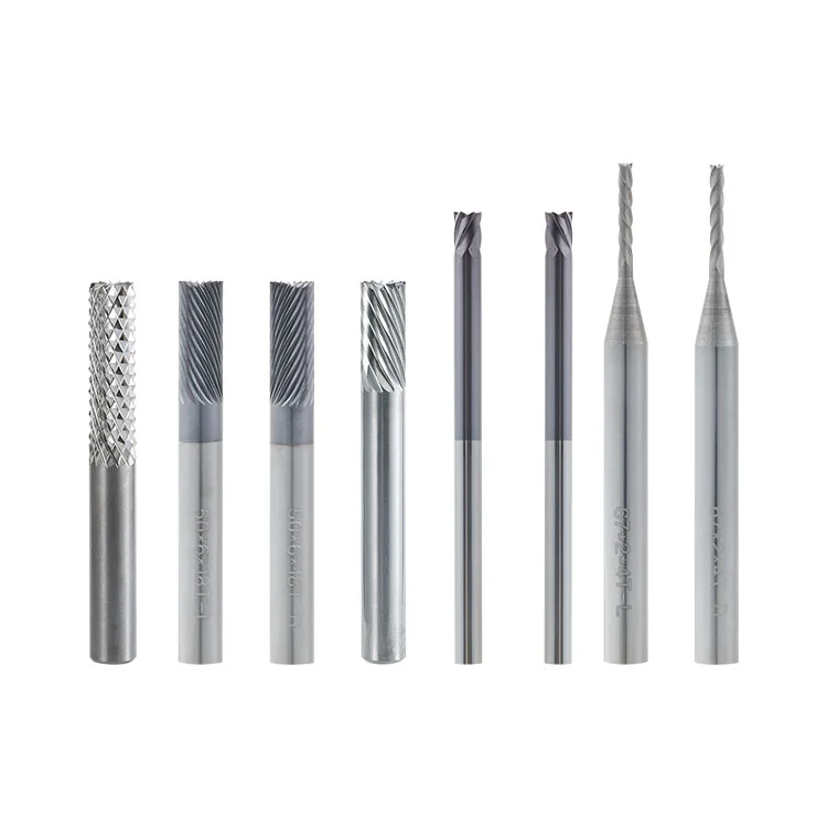
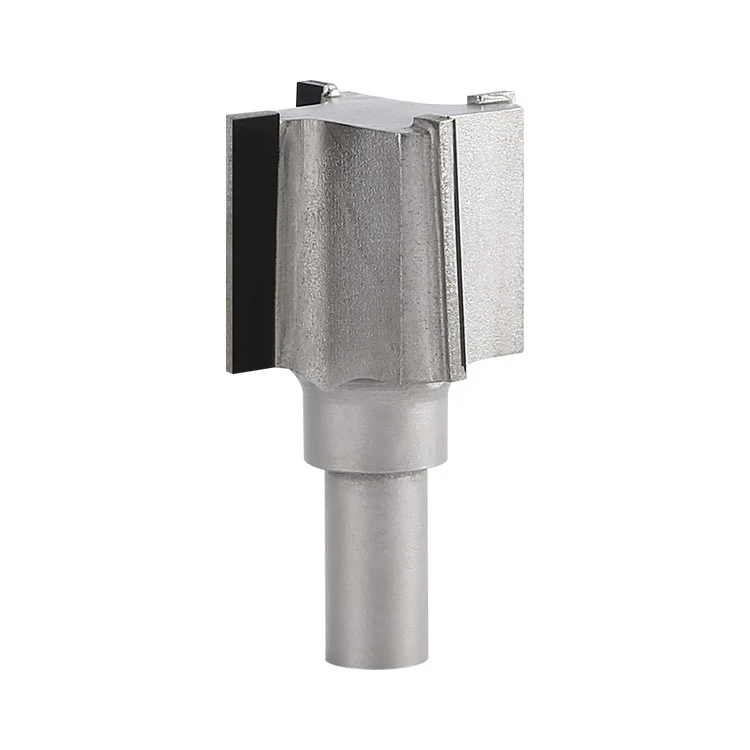
Winway supplies the PCD PCB Straight Corner Radius Cutter for wholesale and customized orders. The shank of the tool body is made of alloy steel, and the cutting edge is welded with polycrystalline diamond with precision ground finish. In radius machining, it can complete straight-edge cutting and edge radius forming in a single pass, eliminating the secondary chamfering process. It is specially designed for highly abrasive materials such as fiberglass boards, multi-layer circuit boards and insulating composite materials. It solves pain points including fast wear of ordinary carbide cutters, surface fuzzing and inconsistent radius, and is widely used in the precision machining of PCB, new energy insulation boards and engineering plastics.
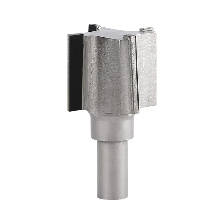
PCD PCB Straight Corner Radius Cutter: A precision forming milling tool with alloy steel as the shank substrate, welded with polycrystalline diamond (PCD) as the cutting edge. Its cutting edge is pre-finished and ground. It is used for one-step machining of straight-edge milling and corner radius forming on plates by radius-milling machines.
1. The spindle of the radius-milling machine drives the tool to rotate at high speed, and the PCD composite cutting edge contacts the edge of the plate workpiece.
2. The cutter feeds along workpiece contour, removes sharp-angle material and completes straight-edge milling and corner R-angle forming in one pass.
3. Chip flutes discharge resin and glass-fiber chips smoothly, reduce scratch and thermal-burn risk on plate surface caused by chip friction.
4. Benefiting from ultra-hard PCD cutting edge, the tool wears slowly when cutting glass-fiber-filled materials, guarantees stable dimension of R-angle in mass-volume processing.
| Item | Parameter Specification |
| Product Name | PCD PCB Straight Corner Radius Cutter |
| Cutting Outer Diameter | 30mm |
| Total Length | 65mm |
| Shank Diameter | 10mm |
| Teeth Number | 4 |
| Cutting Edge Length | 25mm |
| Cutting Edge Material | PCD Polycrystalline Diamond |
| Shank Substrate Material | Alloy Steel |
1. PCD PCB Straight Corner Radius Cutter is used for profile milling and board-corner rounding for FR4 multi-layer boards and glass-fiber boards in the PCB industry.
2. Machining of various glass-fiber reinforced insulating plates and synthetic composite plates.
3. Precision edge milling and R-angle forming for engineering plastics, acrylic and bakelite plates.
4. Precision processing for new-energy insulating plates, tooling plates and fixture plates.
1. Machining carbon steel, iron and other ferrous metal workpieces; PCD material has relatively low toughness and is easy to suffer cutting-edge chipping when cutting ferrous metal.
2. Workpieces mixed with massive hard metallic impurities or coarse hard particles, which will bring impact damage to PCD cutting edge.
3. Excessive single-pass cutting depth exceeding allowable cutting-edge limit, resulting in PCD brazing-zone chipping and substrate deformation.
4. Equipment without effective chip-removal system; accumulated glass-fiber dust will accelerate cutting-edge wear and scratch workpiece surface.
5. Machining under condition of large spindle run-out or loose fixture; vibration will easily cause PCD edge chipping.
6. Long-time heavy-load dry-cutting without heat dissipation; high temperature may cause PCD brazing layer debonding and alloy-steel substrate thermal deformation.
1. ❌ Misunderstanding: PCD cutters can process all kinds of materials Correction: PCD is suitable for glass-fiber-filled PCB, composite and plastic materials. Ferrous metal and large hard impurities will damage diamond cutting edge.
2. ❌ Misunderstanding: Larger cutting depth brings higher production efficiency Correction: Layer-by-layer cutting shall be adopted. Excessive single-pass depth may cause chipping on PCD brazing position and substrate deformation under over-stress.
3. ❌ Misunderstanding: No need to check spindle run-out when using PCD tools Correction: PCD blade is brittle; excessive spindle run-out will lead to frequent edge chipping, which will greatly shorten tool service-life.
1. Do not start cutting under excessive spindle run-out, dirty or worn collet; vibration will chip PCD cutting edge.
2. Forbid tool collision or starting spindle with unclamped workpiece.
3. Chip-blowing / dust-collection system must be kept running; glass-fiber dust abrades PCD edge and accelerates wear.
4. Forbid emergency stop and sharp feed-direction change under high-speed rotation status.
5. Never exceed maximum allowable single-pass cutting depth; full-depth one-time cutting is prohibited.
6. Prevent cutter from dropping and hard impact. PCD tip is brittle and easy to chip under slight impact; alloy-steel shank may bend after collision.
| Abnormal Phenomenon | Root Cause |
| Plate edge chipping and glass-fiber fuzzing | Large spindle run-out, over-fast feed rate, worn cutting edge, impurities inside plate, insufficient chip-blowing & dust-collection. |
| Unstable R-angle dimension | Poor concentricity, slipping collet, loose workpiece clamping, shank bent by impact. |
| PCD cutting-edge chipping / notch | Tool collision, hard foreign-matter inside workpiece, severe vibration, excessive single-pass cutting depth. |
| PCD insert debonding & falling-off | Over-high cutting temperature, over-load machining, damaged brazing seam, long-time dry-cutting without heat dissipation, substrate thermal deformation. |
| Burnt & blackened plate surface | Mismatched spindle-feed parameter, poor chip evacuation, hot chips scorching workpiece surface. |
| Tool service-life far below expectation | High-glass-fiber workpiece, unreasonable cutting parameters, poor dust-removal effect, deformed shank causing unstable cutting. |
1. Storage: Store individually in special tool-box with cutting-edge protection. No stacking or bare-placed, avoid collision impact.
2. Before operation: Visual check cutting-edge for chipping or crack; clean collet dust; inspect spindle run-out.
3. During machining: Keep dust-collection / air-blowing system working continuously. Periodically inspect R-angle dimension, monitor cutting-edge wear and shank deformation.
4. After machining: Blow away chips and dust with low-pressure air-gun, do not scratch PCD edge with hard objects; inspect PCD edge for micro-chipping.
5. Handling: Only hold the shank part, do not touch PCD cutting tip; prevent dropping to avoid bent shank and tool scrap.
A1: PCD diamond cutting-edge has much higher wear-resistance than carbide. Service-life can be increased more than ten times for glass-fiber plate processing and less fuzzing occurs. Its shortcoming is relatively low toughness; it shall not be used for machining ferrous metal.
A2: Excessive feed rate, large spindle run-out, insufficient workpiece clamping or over-hanging tool length. It is recommended to reduce feed rate and inspect fixture and spindle condition.
A3: Yes. Send back to factory for professional re-grinding service to restore cutting-edge precision after edge wear.
A4: It is not suitable for steel, iron and other ferrous-metal plates. It applies to glass-fiber board, PCB, composite material and engineering-plastic workpieces.
Address
Building 17, Yonglida Tiansheng Industrial Park, No. 50 Gangkou Avenue, Wanjiang District, Dongguan City, Guangdong Province, China
Tel